Do you have questions about the products? Send an email | Send a WhatsApp message
SALE -20 %

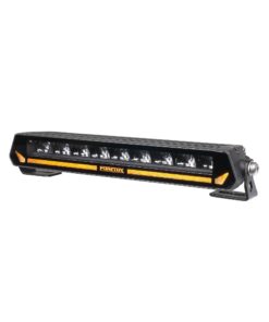
Multi-Switch Panel 10-30V, Purelux
Original price was: 198,41 €.158,57 €Current price is: 158,57 €.
Versatile switch panel for controlling up to 8 electrical devices.
Out of stock
Ask about the product
Ask about a product
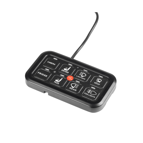
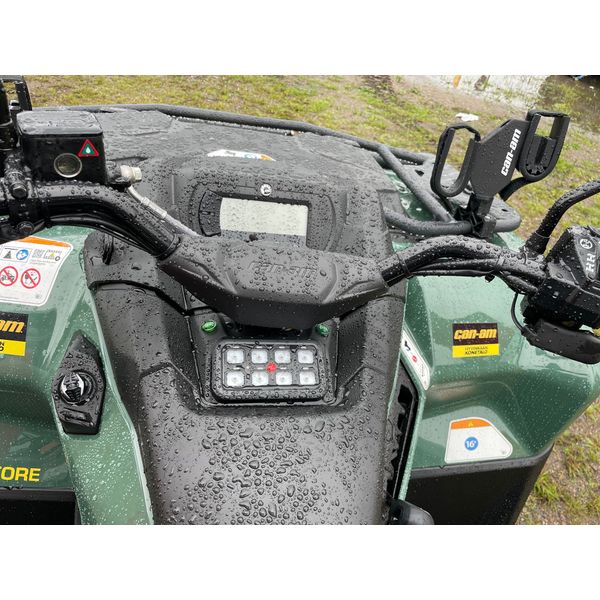
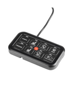
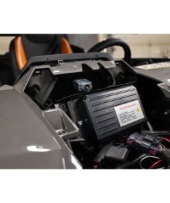
Purelux Multi-Switch Panel is a very versatile and convenient switch panel for controlling up to eight different electrical devices (lights, beacons, engine fan or even a seat heater). The switch panel can be used to control the front, rear and side work lights and the beacon separately, for example on a work machine, and the switches for all the lights are conveniently located in the same place. The lights can be switched on and off individually, and a switch in the centre allows all the equipment mounted behind the panel to be switched off simultaneously. In addition to continuous power, the switches can be programmed to operate as a one-off flash button or as a continuous flashing strobe.
The switch panel has a backlight with three different brightness levels, and a total of 45 different picture labels are included, as well as five black, self-cut labels for marking the switches. This way, the switch for each different device or light can be marked to avoid confusion and the symbol on the switch shines clearly thanks to the backlight.
The switch panel allows all the lights connected behind it to be lit either steadily, momentarily (by pressing a button on the bottom) or flashing. The mode can be changed by pressing and holding the main power switch in the centre of the panel, then pressing and holding the desired button for a moment (the indicator light flashes = mode change). This way, for example, a separate flasher relay is not needed to make the lights flash! In addition, the panel is equipped with a handy memory function, i.e. it turns on the lights in the same mode as before the power was switched off.
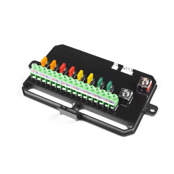
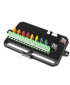
WATCH OUT! The switch panel has a current rating of 600W @12V and 1200W @24V. So the total power of the electrical devices on at the same time must not exceed 600W (or 1200W). Circuits 1 and 2 can withstand a maximum current of 30A, circuits 3 and 4 20A, circuits 5 and 6 10A and circuits 7 and 8 5A. Each circuit has its own fuses in the control box.
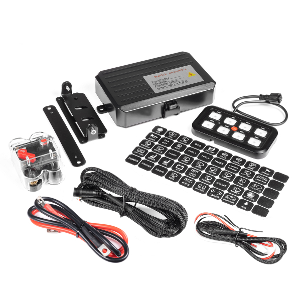
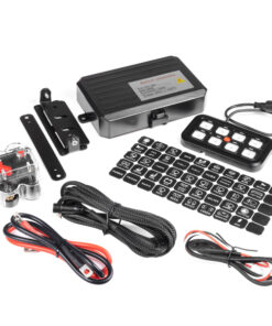
Contents
- Switch panel (8 switches)
- Control box
- Residual current circuit breaker (60A)
- 4-pin cable (for switch panel), 300 cm
- 2-pin cable
- Current cable
- 2 different fixing brackets for switch panel
- Mounting bracket for the control box
- 50 labels
- Screw set
- Binding strips
Technical specifications
- Which: Switch Panel Purelux Multi-Switch Panel, 10-30V
- Purpose: to operate up to 8 electrical devices from the same switch panel
- Allows you to operate e.g. auxiliary lights, side and rear work lights and beacon panel separately
- Operating voltage: 10-30 V
- Power rating: 600 W @12 V, 1200 W @24 V
- Maximum current: 60 A
- Complete with 50 labels
- Switch panel size: 116 x 66 x 14 mm (L x H x W)
- IP rating: IP67
- Approvals: CE marked
- More:Panel memory function
- Warranty: 12 months
.
.
Connection instructions
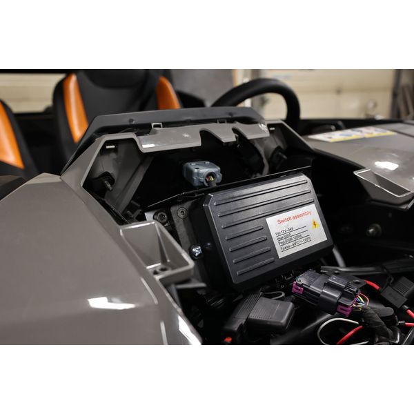
Power: Connect the main power cable through the circuit breaker to a battery or other fixed power point and the other end to the marked power point on the contland roller box. Connect one end of the earthing cable to e.g. the vehicle chassis or other fixed earthing point and the other end to the marked earthing point on the control box.
Connecting the switch panel: Connect one end of the supplied 4-pin cable to the switch panel, the other end to the marked plug in the control box.
Actuating power: The control box can be supplied with actuating power depending on the desired installation: if it is not desired that the equipment installed behind the switch should operate without the vehicle being running, it is advisable to connect the actuating power cable to, for example, a parking light bulb or the base of the ignition switch. If, on the other hand, it is desired that devices connected to the panel (lights, etc.) can be operated even when the vehicle is switched off, the excitation current should be connected directly to the plus pole of the car battery or other fixed power supply, for example.
Connect the red/white 2-pole excitation power cable to the control box: the red wire is the excitation power wire, and the white wire controls the brightness of the switch panel backlight. Use the instructions below to connect the red wire to the appropriate location.
Connecting the lights (or other electrical devices): Connect the desired lights to outputs 1-8 on the control boxes. Note the maximum current allowed for each circuit, and connect the device to be connected to the appropriate power output.
Relay tip: If the power of the light(s) exceeds the maximum power of the contland roller (240W @12V), the contland roller can also be used to control a relay, in which case the current required by the lights (or part of the lights) will pass through the relay/relay harness, with only the excitation current coming from the contland roller. In this case, instead of the light’s power cable, only the excitation cable of the relay/relay harness is connected to the output (P1-P4) from the contland roller.
This way, for example, the rear and side lights can be provided with 230W of power, and the front lights, whatever their power, are connected behind their own relay harness. In this case, the front lights are powered by the relay and do not require power from the contland roller.
Additional features of the switch panel – In addition to continuous power, the switches can be programmed to operate as a one-time flash button or as a continuous flashing strobe-tomode:To change the operating mode, follow these steps. Step 2: Select the switch for which you want to change the operating mode. Step 3: Hold down the power button and press the selected switch at the same time, the LED light on the switch will flash, indicating that the operating mode has been changed. Step 4: Test the operation. If the operating mode has not changed, turn the switch panel back on and repeat steps 1 to 3.
| Home Delivery | 30,00 € |
|---|
Related products
37,45 €
Wide, wide illuminating beam pattern and 2800 lm light output.
30,28 €
Wide beam pattern and 2880 lm light output.
SALE -15 %
Out of stock
Original price was: 102,79 €.87,65 €Current price is: 87,65 €.
Super low panel with 3930 lm light output.